Digital Scale
In this workhop we will learn how to how to make a digital scale to measure distance.
Problem Statement
In order to measure distance from some physical thing we can use scale or measuing tap, but what if we need to need to take continous measurement and analyize the differnce, or we need to make an action depends on the distance like water level, waste level, oil level etc. repetitive continous measurement cost too much human resource.
Idea
What if, we have a system that can be continually monitor the level and make actions.
Solution
Build a device that can be controled wcontinually monitor the level and make actions like getting notification when a waste bin is full or getting a notification that can be help to prevent flood by monitoring water level..etc
Prototype Building
- Build a device that Measure distace and displayed on LCD Screen
Here we are using an Arduino as controller and HCSR04 Ultrasonic Module to measure the distance and 16x2 LCD Display to Display the Distance.

Things we need
- Arduino Uno
- HCSR04 Ultrasonic sensor
- 16x2 LCD Module
- 10k ohm potentiometer
- 220 ohm resistor
- Jumper Wires
- Breadboard
Ultrasonic Sensor
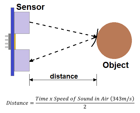
Ultrasonic sensors work by sending out a sound wave at a frequency above the range of human hearing. The transducer of the sensor acts as a microphone to receive and send the ultrasonic sound.
It emits an ultrasound at 40 000 Hz which travels through the air and if there is an object or obstacle on its path It will bounce back to the module. Considering the travel time and the speed of the sound you can calculate the distance.
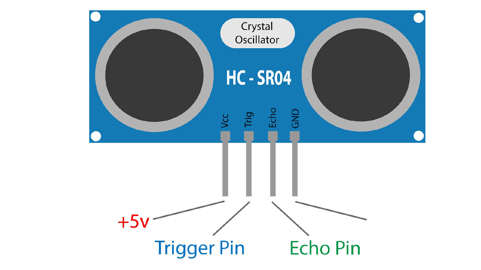
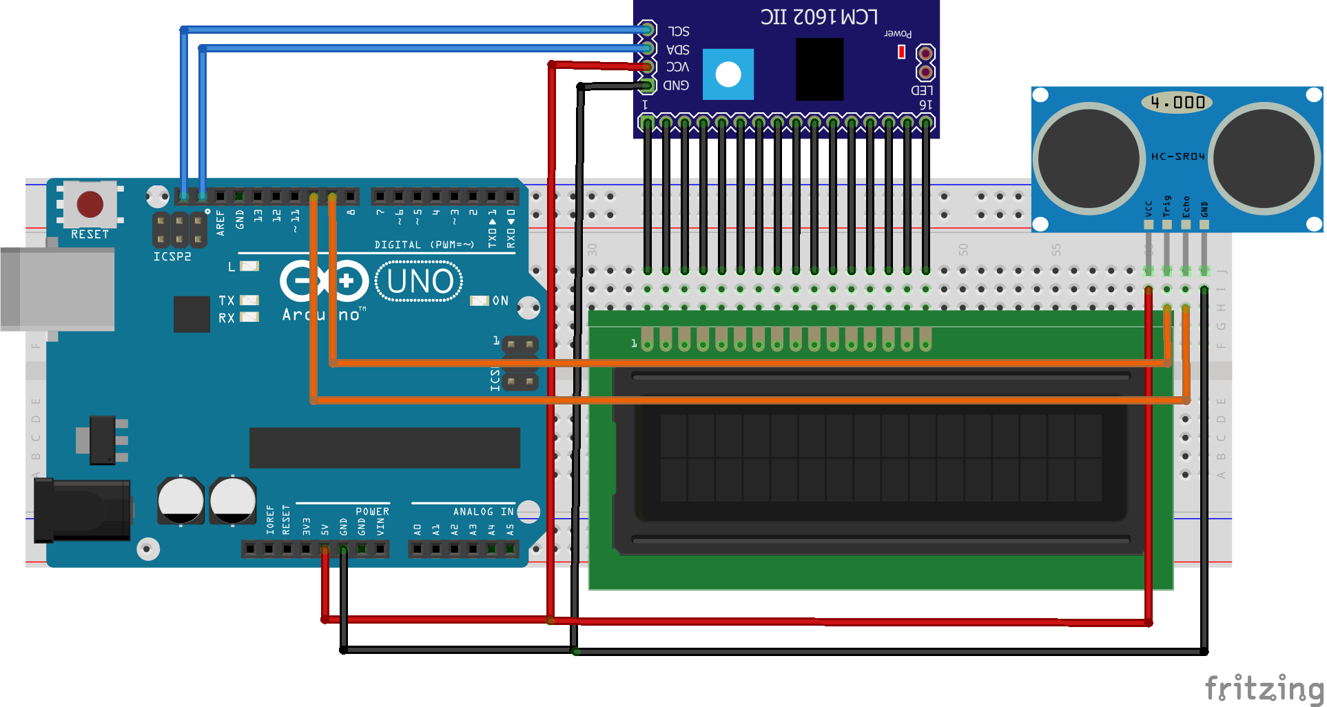
The HC-SR04 Ultrasonic Module has 4 pins, Ground, VCC, Trig and Echo. The Ground and the VCC pins of the module needs to be connected to the Ground and the 5 volts pins on the Arduino Board respectively and the trig and echo pins to any Digital I/O pin on the Arduino Board.
LCD Module
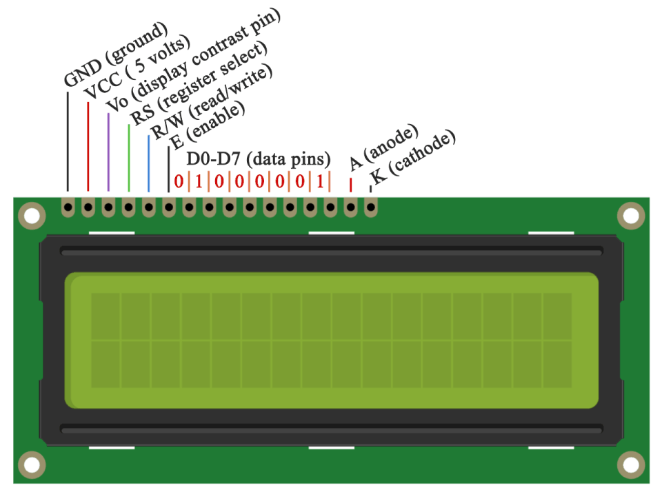
An LCD is an electronic display module which uses liquid crystal to produce a visible image. The 16×2 LCD display is a very basic module commonly used in DIYs and circuits. The 16×2 translates o a display 16 characters per line in 2 such lines. In this LCD each character is displayed in a 5×7 pixel matrix.
Pin Description
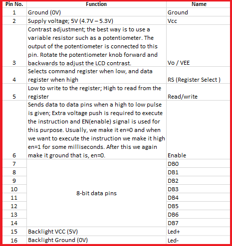
Step 1: Arduino Setup
1.1: Install Arduino IDE
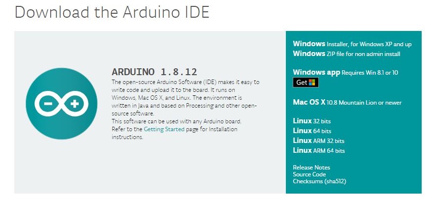
Download the Arduino IDE and install it on your computer.
1.2 walk-through the Arduino Introduction page to learn basics
If you are new to the arduino system, you can learn the Arduino basics from here , after reading then go to the next step.
Step 2: Programming
2.1 Algorithm
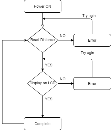
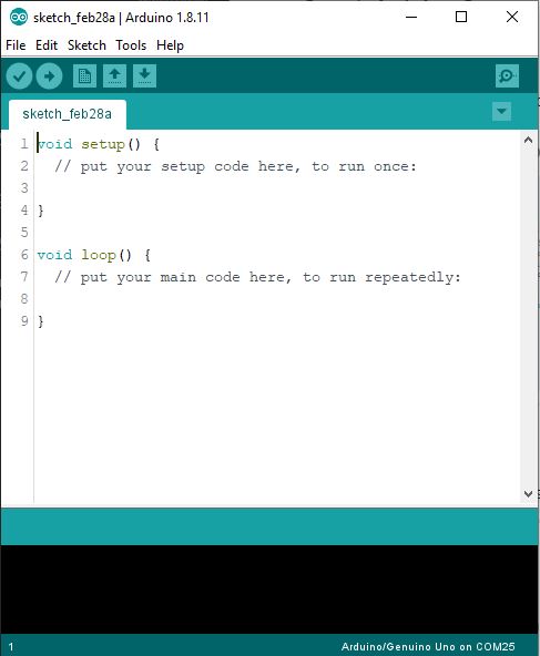
2.2 Open Arduino IDE and Start a new Sketch
2.3 Read then Copy and Paste the Code
Tesing HCSR04 UltraSonic Module
const int trigPin = 9;   // defines Pin 9 as Trigger Pin
const int echoPin = 10; // define Pin 10 as Echo Pin

//define Variables
long duration;
int distance;


void setup() {

  pinMode(trigPin, OUTPUT); // Sets the trigPin as an Output
  pinMode(echoPin, INPUT); // Sets the echoPin as an Input
  Serial.begin(9600);     // Starts the serial communication

}
void loop() {

  digitalWrite(trigPin, LOW);     // Clears the trigPin
  delayMicroseconds(2);          // wait for 2 micro second
  digitalWrite(trigPin, HIGH);  // Sets the trigPin on HIGH state
  delayMicroseconds(10);       // wait 10 micro second
  digitalWrite(trigPin, LOW); // Sets the trigPin on LOW state

  duration = pulseIn(echoPin, HIGH); // Reads the echoPin, returns the sound wave travel time in microseconds

  distance = duration * 0.034 / 2;  // Calculating the distance

  Serial.print("Distance: ");
  Serial.println(distance);     // Prints the distance on the Serial Monitor

  delay(500);                  // wait 500 milli second
}
2.4 Compile the code
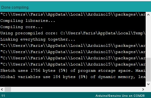
You can Compile and verify your code by clicking the Verify button on Arduino IDE, this process will check syntax errors.

after successful compilation you can see Done Compiling
2.5 Upload the code into Arduino uno
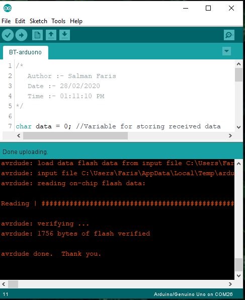
After successful compilation we can upload the code into Arduino Uno Devlopment board. for that we need click **Upload button.

before upaloading we need to select the devlopment board from the from Arduino IDE Tools -> Board and Port from Arduino IDE Tools -> Port.
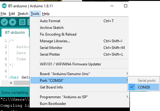
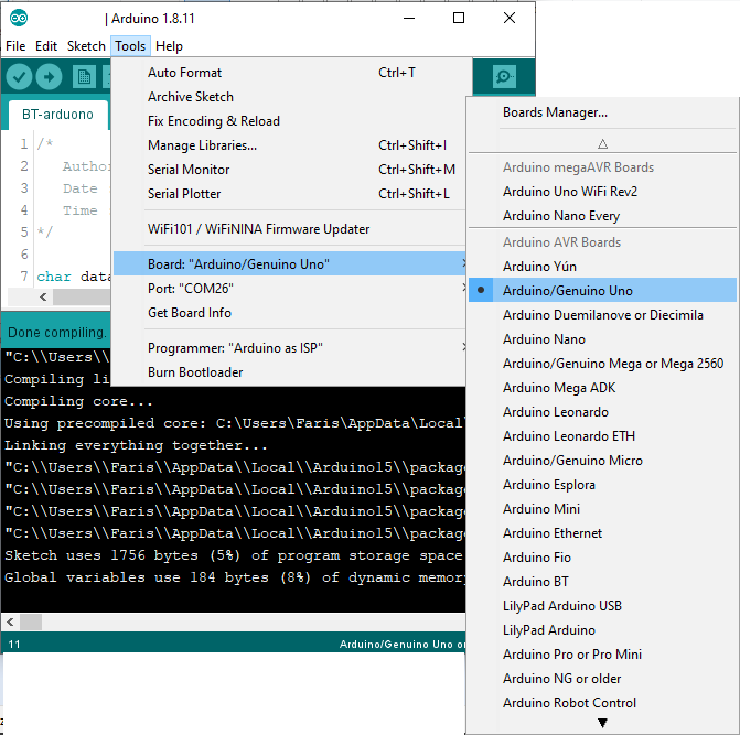
here I selected Arduino Uno as board and COM26 as Port.
Then click Upload
2.5 Connect the HCSR04 Module to Arduino
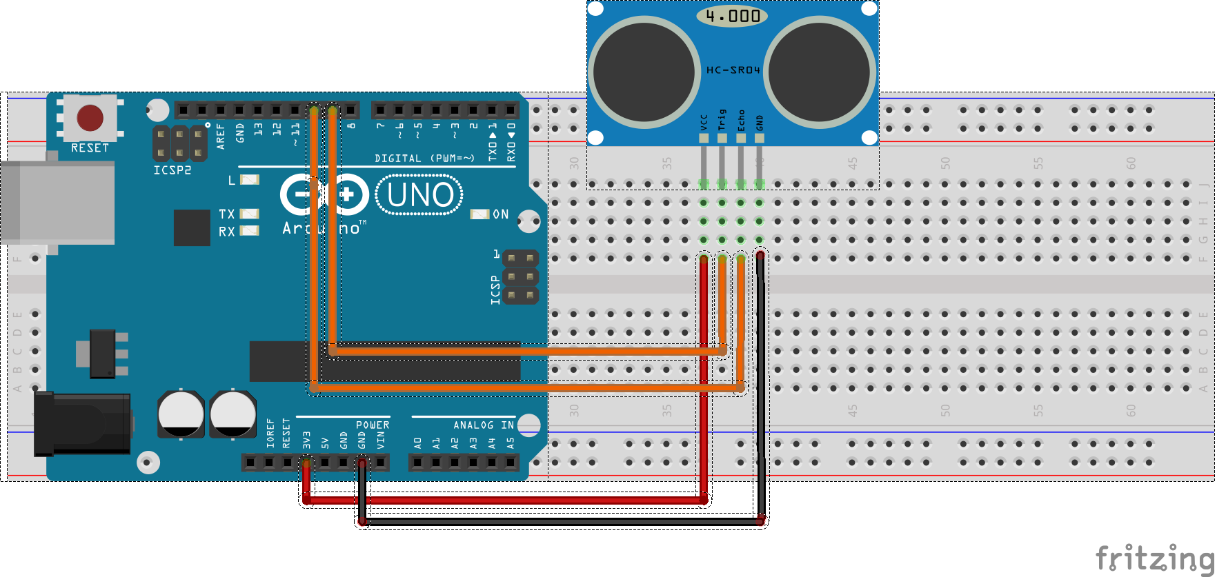
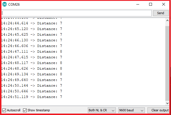
We can test the project from halfway without LCD module by using Serial Monitor .
After connecting the HCSR04 on arduino connect the USB cable and Open Serial Monitor .

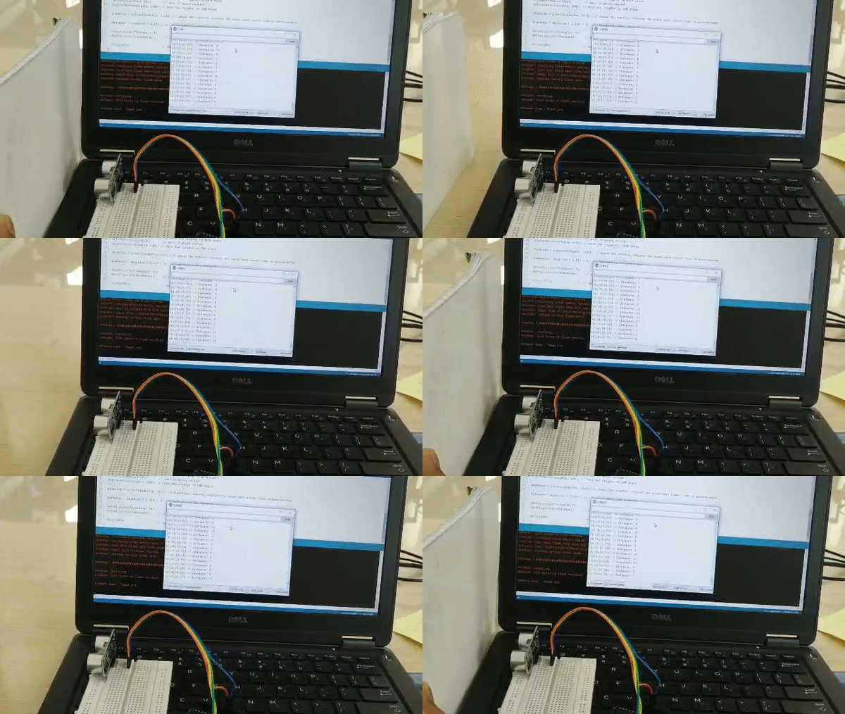
We can see the distance measured from the Ultrasonic sensor from the Serial Monitor Window
Tesing LCD Module
Here we are using LCD Module with 12C addons for I2C Communication , which will only need two wires for communication, in other way we need to use 14 pins.
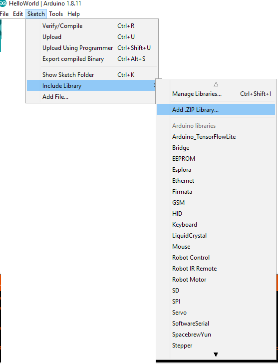
Since the I2C is a addon we need to insert the library on Arduino IDE first. For that first downlaod the Arduino-LiquidCrystal-I2C-library.zip, Then click Sketch -> Include Library -> Add .ZIP Library
then select the .Zip file and click open.
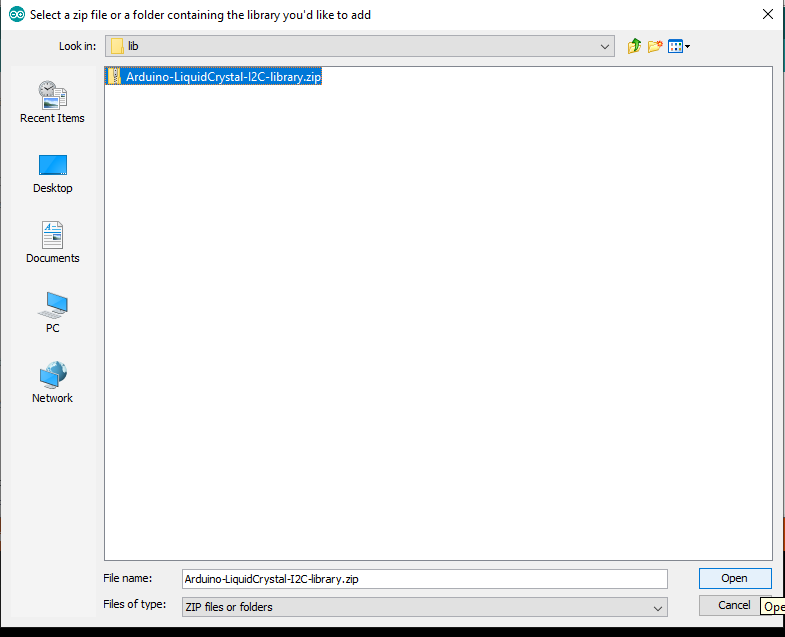
now we successfully added the I2C library.
Uplaod and Compaile Code
#include <Wire.h>
#include <LiquidCrystal_I2C.h>

// Set the LCD address to 0x27 for a 16 chars and 2 line display
LiquidCrystal_I2C lcd(0x27, 16, 2);

void setup()
{
	// initialize the LCD
	lcd.begin();

	// Turn on the blacklight and print a message.
	lcd.backlight();
	lcd.print("Hello, world!");
}

void loop()
{
	lcd.setCursor(0, 1);
  lcd.print(millis() / 1000);

}
Connect LCD Module with Arduino
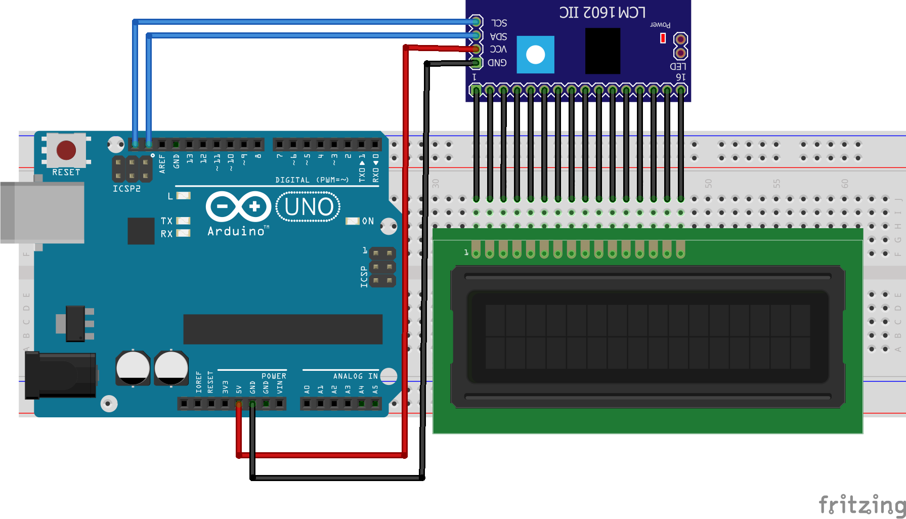
Demonstrates the use a 16x2 LCD display. The I2C LiquidCrystal Module comes with 4-pins and connect them with follwing model.
- LCD SCL - Arduino SCL
- LCD SDA - Arduino SDA
- LCD GND - Arduino GND
- LCD VCC - Arduino VCC
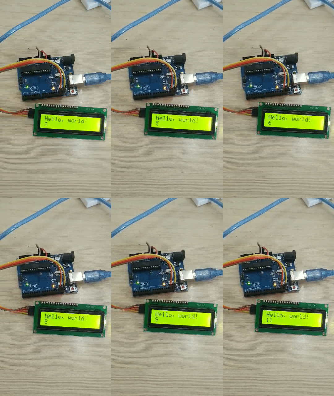
This sketch prints “Hello World!” to the LCD and shows the time.
Step 3: Combine both HCSR04 and LCD Module
We tested both and now we need to combine the both hardware and progrmmes into one.
3.1: Upload code.
#include <Wire.h>
#include <LiquidCrystal_I2C.h>

// Set the LCD address to 0x27 for a 16 chars and 2 line display
LiquidCrystal_I2C lcd(0x27, 16, 2);

const int trigPin = 9;   // defines Pin 9 as Trigger Pin
const int echoPin = 10; // define Pin 10 as Echo Pin

//define Variables
long duration;
int distance;


void setup() {

  pinMode(trigPin, OUTPUT); // Sets the trigPin as an Output
  pinMode(echoPin, INPUT); // Sets the echoPin as an Input
  Serial.begin(9600);     // Starts the serial communication

  // initialize the LCD
  lcd.begin();

  // Turn on the blacklight and print a message.
  lcd.backlight();
  lcd.print("Digital Scale-cm");

}
void loop() {
  lcd.setCursor(0, 0);
  lcd.print("Digital Scale-cm");

  digitalWrite(trigPin, LOW);     // Clears the trigPin
  delayMicroseconds(2);          // wait for 2 micro second
  digitalWrite(trigPin, HIGH);  // Sets the trigPin on HIGH state
  delayMicroseconds(10);       // wait 10 micro second
  digitalWrite(trigPin, LOW); // Sets the trigPin on LOW state

  duration = pulseIn(echoPin, HIGH); // Reads the echoPin, returns the sound wave travel time in microseconds

  distance = duration * 0.034 / 2;  // Calculating the distance
  //String dist = distance + "cm" ;
  Serial.print("Distance: ");
  Serial.println(distance);     // Prints the distance on the Serial Monitor

  lcd.setCursor(0, 1);          //Set cursor to second line
  lcd.print(distance);          // Print distnace on LCD

  delay(500);                  // wait 500 milli second

  lcd.clear();                //Clear the LCD.
}
Wiring
Final Demo

ToDO
-
Add button and measure only when the button pressed.
-
Add buzzer and trigger when a speacial requirment.
-
Designa and 3D Print Enclosure.
Thank You, Hope you enjoyed!
Please share your feedback.
